Here are some photos of existing airway beacons, contributed by Dick Merrill.
Leadville, CO airport/airway beacon
The Leadville beacon is on the grounds of the Leadville airport and was probably part of the airway beacon system. It is identical to an airway beacon except for the green lens. (Airway beacons were white on both sides while airport beacons are white and green.)
Longview, TX airway beacon
The Longview beacon is in the yard of a farm off of Highway 59 just north of Longview, Texas. The light is gone, but the tower is all intact.
Beacon 23 near Kingsport, TN
The last photo is of Beacon 23 near Kingsport, Tennessee on Chimney Top Mountain. It can be seen from I-81 but it is not obvious; binoculars help.
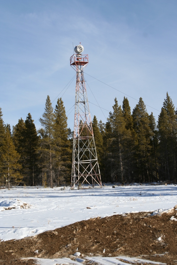
The photographs of this beacon site were contributed by Dean Draper. The site is located in Millard County, Utah, about 20 miles southwest of Delta. Also in the same location is the NGS triangulation station BEAK (KO0428).
Please leave a comment if you have more information about this beacon, perhaps its number or any details of its history.
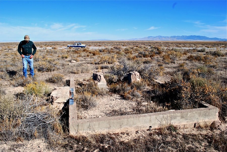
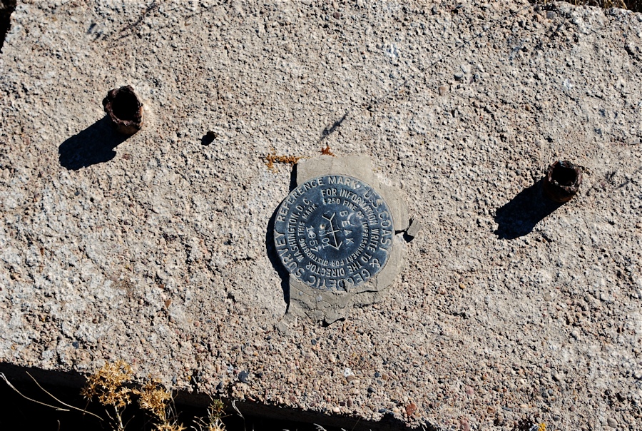
Remains of beacon near Delta, UTBEAK RM 1 at beacon site near Delta, UT
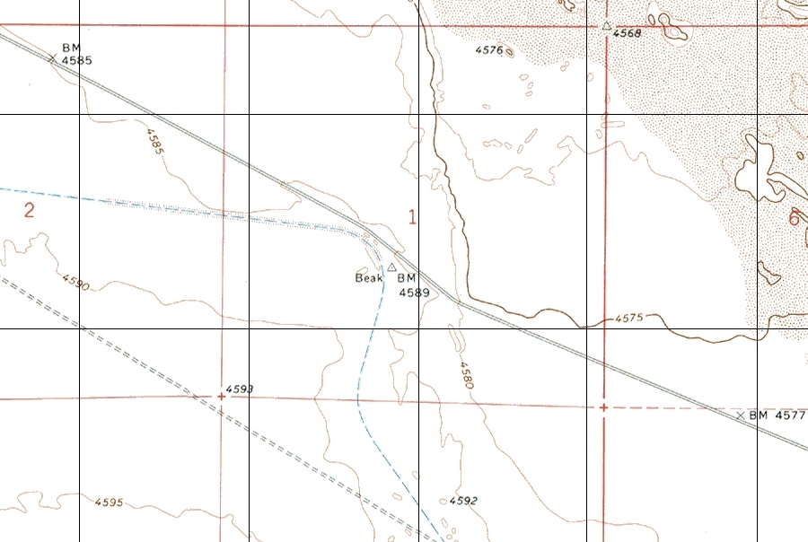
A USGS topo map of the area shows the triangulation station, but no beacon. Could the designation BEAK derive from the word “beacon”?
On October 26, 2013 I visited the Bowling Green, KY area in an attempt to document the location, and any remaining evidence of Airway Beacon 70; beacon 70 was a lighted beacon on the Dallas to Cincinnati airway. While in the area, I also explored the remains of the Bowling Green AN radio range. The excerpt below from the 1945 Nashville sectional aeronautical chart shows the Bowling Green radio range located about 5 miles southeast of the Bowling Green airport. Beacon 70 is about 10 miles east of the airport, just inside the magenta 10 mile radius ring, surrounding the airport. Airway beacons are shown on charts as a star with two arrows pointing to the next beacon on the airway. Beacon 70 is also west of the Barren River, off of S. Ben Thomas Road. (See Topo map below)
The Beacon 70 site was located using a handheld Garmin 496 GPS receiver and was found at the coordinates shown on the NGS data sheet shown below. The coordinates are 36 56 01.80065(N) and 086 15 32.88192(W). The beacon tower is gone but a concrete slab remains within a small grove of trees. The tower leg locations can be seen but only a small portion of the legs remain as they were cut off close to the slab during abandonment operations. The tower orientation was determined by sighting along the southerly tower leg stubs and was found to be running in a southeast-northwest direction at about 120 – 300 degrees.
A portion of the 1945 Nashville sectional chart showing Beacon 70 and the Bowling Green radio range.A portion of the Polkville 7.5 minute Topographic map showing the location of Beacon 70.Southwest corner of the Beacon 70 foundation slab.
Clump of trees in the left background may have been the location of a generator shack if one was installed. Since the site was adjacent to a county road power was likely from a commercial line.
Remaining stub of the southeast tower leg showing how it was cut off near the slab during removal.
I did not find any trace of the northeast tower stub, but it may have been covered by plant debris or it is possible the slab was poured after tower construction and the missing stub is not covered by the slab. I hope to return to this site soon and clean off the slab and try to find the northeast stub and study any other artifacts present.
Remains of southwest tower leg.Northwest tower stub.View along the southerly edge of slab, camera pointing in the direction of 120 degrees, the southeast and southwest stubs are marked with white cards.
For several months I have been looking for the location of Tennessee Beacon 25, a lighted airway beacon on the Washington D.C.-Memphis route. I had coordinates taken from the 1945 Winston-Salem sectional chart so the location was approximately within a one square mile area. Examination of topo. maps and aerial photos didn’t help and for a while I was afraid the beacon may have been destroyed during the building of the nearby I-81.
Tennessee has a very good online GIS system of land ownership. I looked for a farm that might have been around when the Beacon was active. The first land parcel I selected was a hit. I called the number for the Osborne family near Blountville, which is south of Bristol and talked to Mrs. Osborne. She knew exactly what I was interested in and when I explained my quest she stopped me and said, "Oh yes that is the light that used to be on the hill behind my sister’s house." I asked if I could come by sometime and look for evidence of its location. She agreed and said stop by anytime.
A portion of the 1945 Winston-Salem sectional chart showing the location of Beacon 25 north of the Tri-city airport.
I was in Bristol late in November of 2012 and called her to arrange a visit. She said she would be looking for me. Her home and the beacon site are off of Shipley Ferry Road south of Interstate 81. As I drove up her driveway I saw her waiting for me at her garage door. I parked and introduced myself. She pointed to the hill behind her sister’s house, and said "that light was on the top of that hill behind my sister’s house." She asked if I wanted her to go up the hill with me and suggested we could drive up the hill in my jeep. She also said her 86 year old sister wouldn’t mind as she was at her exercise class. I thanked her, but said I would walk up the hill. Other than climbing through a barbed wire fence it was an easy trip up the hill. With the leaves off the trees and most of the ground vegetation dead it was easy to find the four tower stubs poking through the leaf debris on the ground. The tower had been located at the very top of the hill. The tower legs were encased in a concrete footer that was above ground level. Other tower legs that I have found did not have any concrete visible above ground, but some were set in a concrete slab, like the one at the Crossville TN airport.
Many airway beacons were located on airports and are still in use today. The beacon on the grounds of the Crossville Tennessee airport is an excellent example of airway beacon construction and photos of the Crossville beacon are included below to show construction details.
Site of Beacon 25; the beacon tower was located on the crest of the hill.Base of the beacon 25 tower. The tower was attached to the four steel posts.Another view of the hill where Beacon 25 was located. View is looking southeast from Shipley Ferry road.Another view of the base, showing how the legs were set in a concrete footer. The legs have 4 bolt holes for tower attachment and a single hole lower down for a brace attachment.These pipes were the base of the ladder that gave access to the top of the tower for light maintenance. Compare to the photo of the Crossville, TN airport beacon base.Close up of the base of the Crossville, TN airport beacon showing the stub set in concrete with the tower attached to by 4 bolts and a single bolt for brace attachment.Another detail view of the Crossville, TN airport beacon tower showing the tubular base for the ladder attachment.
August 15, 2006: The following questions were posed by Angus Stocking, editor of the upcoming book Lasting Impressions: A glimpse into the legacy of surveying, in which several of my benchmark photographs and stories are to be published. I am sure the entire “interview” won’t be used in the book; I think it was simply intended to give Angus enough background information to write a short paragraph about me. But after writing it I could see the value in posting it on my site, both to satisfy the curiosity of some of my regular visitors, and possibly to spark some interest in those just passing through.
How did you get into benchmark recovery, and how long have you been doing it?
I first became aware of benchmarks in January 2002 through a now-defunct geocache called the NGS Benchmark Recovery Cache. I went out that afternoon and found my first mark, a triangulation station called SOUTHSIDE, not more than a mile from where I was living at the time. It wasn’t until several months later that the Benchmark Hunting section of Geocaching.com went online, but once it did, I was hooked. And I already had found several more marks in the meantime. From the beginning, I was interested in learning how I could contribute to NGS, and I was pleased to find that they welcome and value my observations. I have currently submitted to their database well over 100 official recovery notes.
What are your motivations?
First and foremost, I’m motivated by discovering the connections these marks give me to surveyors and all others who may have seen them and worked with them through the decades. Investigating these marks takes research, patience, and an eye for the little clues that remain long after the most obvious structures and pathways become victims of time and progress. I am also inspired by the fact that I can contribute to the ever-growing NGS database and that my words and measurements will be useful for years in the future. I also have personal motivations. Benchmark hunting has pushed me to climb to mountain summits with beautiful vistas and creep into hidden city corners I never would have seen otherwise, has introduced me to Monica Lewinsky’s apartment building and C. S. Peirce’s estate, has encouraged me to hike along the Appalachian Trail and the Long Path. I’ve become somewhat a collector of experiences, and my memories, stories and digital photos are more precious than any tangible souvenir. I’ve developed my photography, writing and map-reading skills; have researched old buildings, abandoned streets and rail lines; and have improved my physical health.
What are your goals re: benchmark recovery?
I intend to continue searching for and documenting marks for a long time to come. I aim to maintain a high level of care in documenting the marks I find, so that my entries into the NGS database will continue to be of value to professionals. I have kept full photographic documentation of each mark I’ve found and intend to submit these photos to the database as well, when provisions are made for such entries.
About how many benchmarks would you say you’ve recovered?
My current count is 315, which in addition to simple elevation benchmarks includes marks I’ve demonstrated to be destroyed, as well as triangulation stations (whose auxiliary marks I do not count separately unless they have their own PIDs). I don’t go for the quick finds and big numbers like some “hobbyist” hunters do. I prefer to take my time and do a complete recovery, as well as to seek out some of the more obscure marks. Marks that are not found often require more work than the marks that are easy finds, but they aren’t included in our totals. For various reasons not all marks I find are reported to NGS, the most common of which being that many marks are USGS-only, or there have been no changes to the marks’ descriptions or status in the past year.
What are some notable experiences you’ve had?
The stories are lengthy, but just for some examples: I’ve found marks with errors in their descriptions or measurements, which I was able to note to NGS. I’ve met people who were on-site when triangulation stations were set on their property, and who were all too happy to help me with my own recoveries. I’ve found a bolt set in 1865 which is still in great condition today. I’ve also been challenged, chased away from highway shoulders, and watched with suspicion. Probably the best experiences I’ve had have been when I use the clues I find at the site and the old recovery notes to piece together where a tricky mark must be located, and then poke around in the dirt or shrubbery, and actually find it!
And just for background, what’s your day job, and what are some of your other interests?
I work as a computer systems technician and programmer for an academic library. My main interests are website development, railroads and trolleys, photography, local history, and many outdoor pursuits (hiking, mountain biking, hunting, rock climbing).
Why chocolate benchmarks? While browsing web sites last year I came across some silicone molding compounds that I thought would be fun to play with. I wasn’t sure what to use them for, but it occurred to me that it might be fun to make molds of benchmarks, and then create chocolate treats.
Then I started thinking (as did others around the same time, as evidenced by this Geocaching.com forum thread) that a similar process could be used to make a mold of a mark still in its setting if there was something special about it. (Or if you’re really into it and have a lot of spare time, I suppose you could make a mold of every mark you find and start a collection.) Here is the process I used to create my chocolate benchmarks.
1. Find a Benchmark
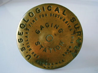
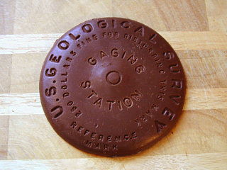
Unused gaging station disk
This may be the hardest part! I happen to have quite a few survey mark disks of various types, most of which are unused disks I acquired from surveyors or others in related fields. One was a Destroyed mark that had to be removed from its setting. I also have several 1-inch replica pins such as can be ordered through Mountainclimb.com. You may even want to modify the process and capture impressions of marks in the field.
The disk I’m using for my demonstration was never used in the field. It was sent to me by a USGS employee with whom I’ve corresponded on an urban exploration forum.
Make sure the disk is clean before making the mold.
2. Make the Mold
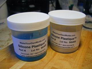
Jars of silicone molding material. Possible molding materials abound, depending on how much time you have to make the mold, what you plan to do with it, and how long you’d like to keep it.
I chose Culinart’s Silicone Plastique, a food-safe silicone molding compound, because I planned to use the molds for edibles. I also liked the fact that the silicone will produce flexible molds that are heat- and cold-resistant.
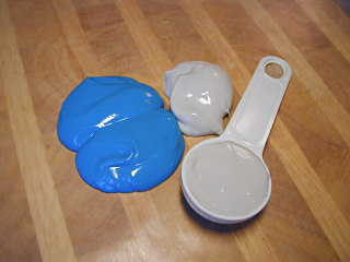
a. Measure the molding compound
It’s almost like baking. For this four-inch disk, I used approximately 2.5 tablespoons of each component. The catalyst (blue) and base (dull white) need to be mixed in equal parts.
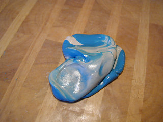
b. Mix it together
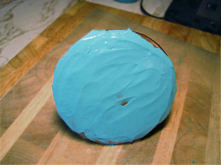
This still needs to be mixed and kneaded some more. The components need to be mixed until a uniform light-blue color is reached. I do this slowly so I don’t introduce too much air into the mixture. Once the two are mixed, you’ve got about twenty minutes to work and an hour until the silicone fully cures. It’s sticky, so I lined the board with waxed paper.
c. Fill in the details
Spreading on a thin layer. It’s best if you fill in the fine details first with a thin layer. Be sure not to trap air bubbles beneath the silicone.
An offset spatula might help, or just use your fingers.
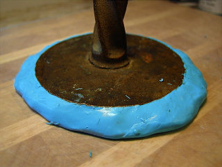
d. Complete the mold
Smooth up the sides. Form a 1/4-inch thick patty from the remainder of the silicone and press the mark down into it. Then smooth the sides of the mold up to conform to the edges of the mark.
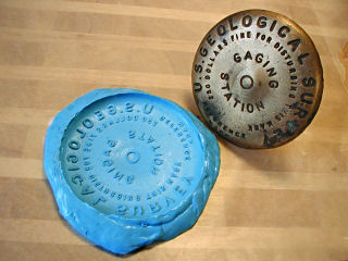
The finished mold. Let it sit for at least an hour for the silicone to cure, then peel away the mold. (Test it first by trying to press a fingernail into the outer edge of the mold, just to make sure it has solidified.)
3. Make the Chocolates
a. Melt the chocolate
For the best look and taste, buy real chocolate and learn how to temper it. Did I do this? No, at least not yet. I used quick-melting candy wafers that are available in most arts & crafts stores.
If you’re using candy wafers, just follow the manufacturer’s directions. Generally they’ll melt in a few seconds in the microwave. Or if, like me, you don’t have one of those newfangled contraptions, they’ll melt equally well in a double boiler. And if, like me, you don’t have a real double boiler, you can make one out of a shallow metal bowl set atop a deep pot half-filled with simmering water. You’ll figure it out.
b. Fill the mold
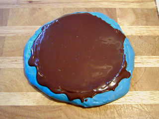
Filled mold
Pour the melted chocolate slowly into the mold. Lifting the mold a few inches and dropping it on the counter several times will help release any air bubbles that may have formed.
As you can see, some chocolate spilled over the sides. It’s very easy to remove the excess after the chocolate hardens.
c. Chill and unmold
The finished disk!Refrigerate 20-30 minutes or until chocolate has hardened, and then pop out your chocolate benchmark! They go very well with tea and shortbread cookies.