7 Myths About the Lighted Airways

Often-repeated misconceptions and historical fallacies regarding airway beacons and concrete directional arrows

by David M. DuPree

1. MYTH: The airway beacons were dismantled when the U.S. entered WWII to prevent enemy forces from using them for navigation.

As America began preparing for war in the late 1930s, the number of airway beacons continued to increase, peaking at the end of 1941 and remaining relatively constant from year to year for the duration. From 1939 through 1941, 357 rotating airway beacons were added to the nation’s lighted airways. Amber Civil Airway No. 8, extending along the California coastal region from Los Angeles to San Francisco, was built during 1941 and continued operating through the war years. Aside from infrequent, localized and brief blackouts, the lighted airways – even the coastal routes – remained operational as a wartime necessity. During blackout exercises, airway beacons were specifically exempt. It wasn’t until the postwar period that the number of beacons returned to the 1937-1938 levels. Between 1940 and 1945, there were more airway beacons operating in the U.S. than at any other time in history.

2. MYTH: The airway beacon towers were scrapped during WWII because the steel was needed for the war effort.

The airway beacons were an essential part of the war effort. Many new beacons were added to the system beginning in the late 1930s (see above). WWII resulted in an immediate and massive increase in air traffic from coast to coast. This included unprecedented levels of military flight training, as well as the movement of personnel and materiel on a grand scale. The light beacons remained indispensible for night navigation throughout the war.

3. MYTH: The large directional arrows were the first navigation aids on the airways and the beacons were added later.

Rotating beacons were in use on the airways as early as 1923. Directional arrows were not introduced until late 1926 or early 1927. Concrete arrows were built only as daytime visual aids to supplement the rotating airway beacons and other site markings.

4. MYTH: Large directional arrows were built and used by the U. S. Air Mail Service.

I have found no evidence that the Post Office Department (U. S. Air Mail Service) ever built or utilized directional arrows on its airways (1918-1926). There is no known record or documented instance of an Air Mail Service pilot relying on large directional arrows for course information. The first concrete directional arrows were built after the Department of Commerce assumed responsibility for the development, construction and maintenance of the federal airways in late 1926. Though used by contract air mail operators, the arrows were not established by the U. S. Air Mail Service.

5. MYTH: Concrete directional arrows were located at all federal airway beacon sites.

Concrete directional arrows were included in construction specifications for airway beacon sites only from 1927 to 1932. However, even during that period not all beacon sites included concrete arrows. In fact, there were entire airways from that period that were not equipped with arrows. For instance, some coastal routes didn’t need large directional arrows for daytime navigation since they were already equipped with the ultimate visual marker – the coastline. As with most aspects of configuring and equipping airways and individual beacon sites, the airway engineers determined whether arrows were needed. In any case, you are unlikely to find a concrete arrow at an airway beacon site built after 1932. Fewer than half of all airway beacon sites included a concrete arrow.

6. MYTH: The concrete directional arrows were illuminated at night.

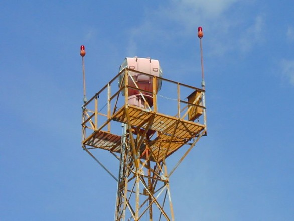
As originally envisioned by the Department of Commerce in 1927, the concrete arrows were to be illuminated by lights mounted overhead on the beacon towers. This was implemented at some sites during 1927, but it was soon determined to be impractical due to several factors. Among other things, the spotlighting was inadequate for making the arrows distinguishable at night, and at remote locations, the limited wattage provided by the on-site generators was increasingly needed for other things, including the newly introduced course lights. The arrows remained in the plans, but they became directional aids for day, visual conditions only.

7. MYTH: The airway beacons were in service for only a few years.

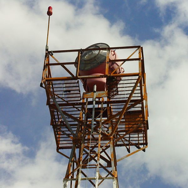
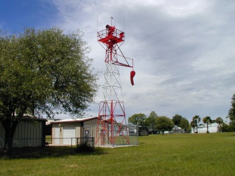
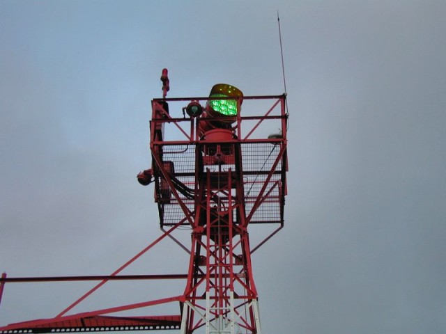
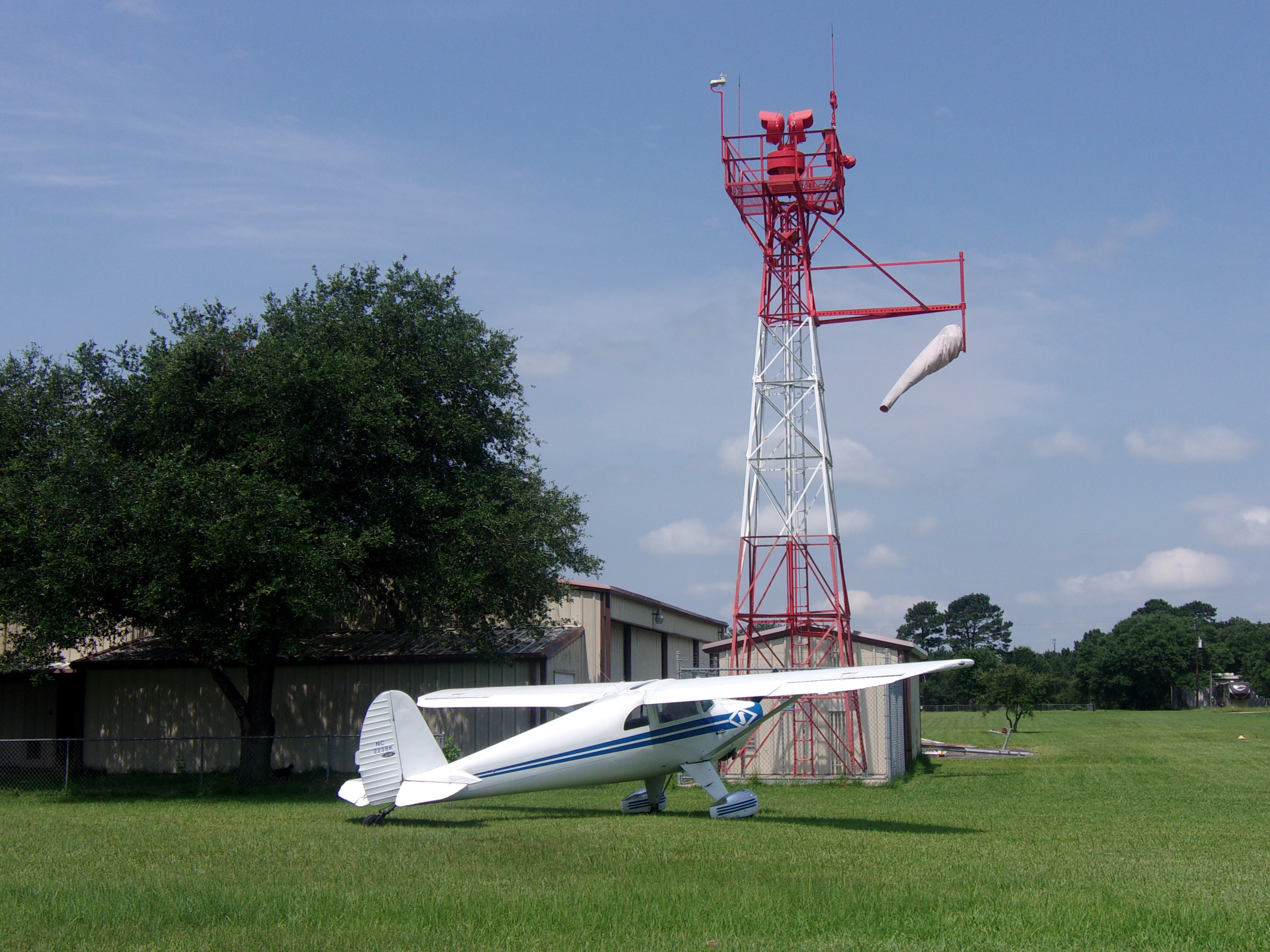
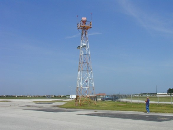
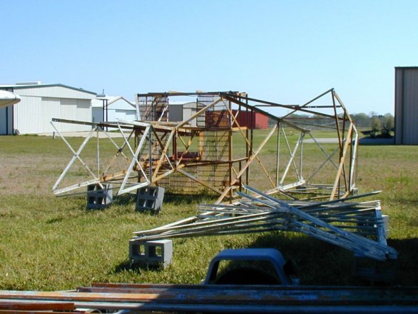
Airway beacons were operated continuously on the federal airways from 1923 until the mid-1960s, a period spanning more than four decades. The decommissioning of airway beacons was a gradual process that began in the 1950s. The final large-scale decommissioning occurred in the mid-1960s. The rotating beacons guided the early Air Mail’s open-cockpit biplanes, the classic planes of the Golden Age, the American air armada of WWII and the majestic postwar prop airliners. The big lights continued serving well into the jet age. A few beacons continued to operate into the 1970s and beyond. The State of Montana still operates several airway beacons, while a few more around the country have been maintained as hazard/landmark beacons. Upon retirement from airway service, hundreds of surplus beacons and towers went to work at airports, where they continued to serve as navigation aids. Refurbished and sometimes updated with high-tech lamps, some of these beacons (and towers) have been operating for more than 80 years!

Download article (.pdf)

Harvey’s “Counterfeit” Beacon

by Harvey Hartman

When I first started erecting my vintage airway beacon tower, I was unaware of its historical significance. I simply wanted this cool old beacon for our airport. Therefore, an exact restoration wasn’t in my original plans. While I DID erect the tower close to its original condition, I took a few liberties to upgrade it in a few structural areas and improve its beacon and electrical system. The control system (still in progress) is being brought up to modern standards and will include a receiver that will allow a pilot to activate the beacon from his/her cockpit prior to landing. (i.e. PCL, or “Pilot-Controlled Lighting” in FAA terminology.)

The Original Vintage Beacon

Crouse-Hinds model DCB-36
The beacon that came with my tower was a 36″ diameter Crouse-Hinds model DCB-36, was double-sided with two very-expensive Fresnel glass lens sets, and was equipped with two 1,200,000cp (that’s 1.2 MILLION candlepower!) bulbs. (One was the in-service bulb and the other bulb was a backup mounted in an automatic bulb-changing mechanism.) Introduced in 1932, this model quickly became the standard beacon for the Federal Transcontinental Lighted Airway System. It also eventually replaced most, if not all, of the earlier beacons as normal wear and tear, as well as storms and vandals, took their toll. (The big DCB-36 is also noteworthy in that it was chosen by the Lighthouse Division of the Department of Commerce in 1936 to upgrade its coastal lighthouses from carbon arc, and acetylene-powered beacons.) However, the venerable DCB-36 design is now 85+ years old and replacement parts are getting hard to find. And those parts that ARE still available are getting very expensive. Therefore, I made the disappointing decision to not reinstall the historic original beacon. Instead, I built a stand-in (a stinkin’ counterfeit, if you will) beacon to put on the tower and the original beacon will be restored and displayed inside my hangar where it’ll be safe.

Building My “Counterfeit” Beacon

Due to my decision to not reinstall the original beacon, I set out to find a replacement beacon. I quickly discovered that new (or even USED) beacons aren’t cheap!!! Not one willing to forfeit quality and style for an affordable price, I elected to design and build my own; a substitute with two priorities in mind. The substitute had to be robust and cheap to maintain/repair, and it must look like something out of the late 1920s – early 30s.

With the tower being a late-1920s model, I decided to model my homemade beacon after the earlier “double-drummed” beacons. (“Double-drum” is slang for beacons that use individual housings, or “drums”, mounted back-to-back to produce the alternating white and green flashes signifying the location of a civilian flying field. The later “Single-drum” beacons such as the DCB-36 used one housing that contained a single bulb in the center with a green lens on one side of the housing and a clear lens on the opposite side to produce the two flashes.

I decided to model my “counterfeit” beacon after the 24″ double-drummed design. However, my fondness for old steam locomotive headlights and America’s glorious 1920-30s Art Deco period may have also influenced my new beacon’s design.

And while it will be virtually impossible to stop the storms and vandals, at least I can make their damage less expensive. Therefore, my stand-in beacon uses common yard floodlights instead of the exorbitantly-expensive high-powered metal-halide bulbs and Fresnel lenses, and its housing is constructed of thick steel instead of cast aluminum like the original. Unfortunately, it was beyond my capabilities to construct a replacement for the original rotator base so I’m reusing it for the time being, but with a steel shield added around it for increased protection.

My new beacon had a humble beginning as an old propane tank which donated its heavy steel end domes to become my new beacon’s backshells.

I then built their mounting yokes and an adapter box that would mate the beacon to the rotator’s output turntable. This completed the basic beacon and its mount.

The Ring Shields were fabricated next and the visors followed. And this was the end result.

A trip to the powdercoaters resulted in this sexy thing! Gratings were fabricated and were added in front of the bulbs to prevent birds from attempting to build nests during the day when the beacon is stationary. From ground level, these “platinum silver” grates look like fluted glass lenses.

The beacons’ elevation angles can be adjusted using this simple jack screw device between 0 degrees (on the horizon) to +20 degrees above the horizon.

We hoisted the “counterfeit” beacon to the top of the tower on 9 April 2016.

And IT WORKS!

Note: The bright white “dot” centered under the beacon in the video is a floodlight that illuminates the windsock when the beacon is operating.

That’s where my “counterfeit” beacon and its tower are as of January 2017. I still have to design and build the PCL system but as the video showed, the beacon can be operated manually for demo purposes.

October 2017 Update

I have recently located and purchased an original late-1920s “double-drummed” Crouse-Hinds DCB-224 airway beacon to replace my “counterfeit” beacon.

I suspect that your first question is probably wondering why I’m replacing the homemade beacon that I spent so much time and effort building to replace my big DCB-36? The simple answer is because it’s not original. It’s incorrect for me to call my beacon tower project a 1920’s Airway Beacon when the beacon itself is a 2016 product. “BUT, (someone is bound to point out) the reason for not reinstalling the DCB-36 was to avoid exposing an historical artifact to potential damage. How is putting up a different antique beacon going to change that?” My reasoning is that while it would be virtually impossible for me to prevent such damage, at least I can make that damage less expensive to repair. I accomplished this by designing my homemade beacon to use common PAR38 landscaping floodlights with their built-in lenses and reflectors, instead of the original beacon’s hugely-expensive Fresnel lenses, and special bulbs. While the large, double-sided design of the 36″ diameter DCB-36 would be difficult to modify, the twin single-sided DCB-24s can successfully use the same PAR38 bulb system as my homemade beacon. This will allow me to say that both my tower and its beacon are alumni of the old Federal Transcontinental Lighted Airway System.

So what’s going to happen to my homemade beacon? Of course, it’ll still serve duty on my tower until the rebuilt DCB-224 beacon is ready to replace it. However, my ultimate plan has always been to have an operational beacon on my tower AND a backup beacon in reserve that would replace the in-service beacon when it needed major repairs that would likely render our airport’s beacon out of service for an extended time. My homemade beacon will serve that purpose well.

For the purists out there, please note that my “PAR38 modifications” are not permanent (i.e. the drums are not drilled, cut, or otherwise irreversibly altered); therefore, the drums can easily be returned to original condition someday. (Unfortunately, the same cannot be said for the propane tank used to create my “counterfeit” beacon.)

—Harvey

July 2019 Update

Harvey's 1947 Luscombe Model 8A "Silvaire" provides perspective as to the size and scope of his tower's restoration project. The 2-seat sportplane has a 35ft wingspan and a 6ft height.
Harvey’s 1947 Luscombe Model 8A “Silvaire” provides perspective as to the size and scope of his tower’s restoration project.
The 2-seat sportplane has a 35ft wingspan and a 6ft height.

The Story Behind Our “New” Beacon Tower

by Harvey Hartman

Restored beacon tower Located at the southern edge of a residential airport on the west side of Houston stands a 42ft tower that is nearing the end of a long relocation and restoration effort. This tower is one of the last few survivors of the 1920s Federal Lighted Airway Beacon System.

Following the completion of the Transcontinental Railroad in 1869, coast-to-coast postal mail was carried by the railroads. While this was a tremendous improvement over the prior carriage by overland stagecoach or by steamship through the Isthmus of Panama, it still required extensive handling of the mail, and its resultant delays, as it was transferred between railroads over the length of the five-day trip.

In 1916, Congress authorized funds for the Post Office Department to begin experimenting with using aircraft for quickly moving high-priority mail long distances and in 1918, additional funds were appropriated to establish experimental airmail routes. For nighttime navigation assistance over these experimental routes, bonfires were spaced at 10 mile intervals and flights through the night became a simple matter of “connecting the dots.”

In 1923, the Post Office began constructing a permanent New York-to-San Francisco transcontinental airway. This airway was initially lighted between Chicago, IL and Cheyenne, WY using a system of steel towers equipped with rotating electric beacons. (The reasoning behind lighting only the middle third of this coast-to-coast airway was that planes departing in daylight from either end would plan to arrive at the lighted portion before nightfall. They would then navigate through the night using the lighted beacon towers until dawn again, and they would continue the final third of their trip in daylight.)

On 1 July 1924, postal authorities began regular around-the-clock operations (establishing the first scheduled air operations in the US). Responsibility of the airway was transferred from the Post Office to the new US Department of Commerce Airways Division upon its creation in 1926 and the construction of additional lighted airways soon followed. A southern east-west transcontinental airway was completed between Los Angeles, CA and Atlanta, GA in 1931 and this route passed through Dallas, TX. Dallas was then connected to Houston by a short north-south airway, then Houston-to-San Antonio, Houston-to-Austin, Houston-to-New Orleans, etc. By 1933, more than 18,000 miles of federal airways were marked by 1,550 beacons spaced at 10 to 15 mile intervals across the US.

Following WWII, the rapid advancement and availability of in-cockpit electronic navigation equipment made the old lighted beacon system obsolete and it was decommissioned and dismantled in the late 1950s and early 60s. The beacons and their towers were then donated to municipal airports for use as airport beacons—one apparently ending up at the La Porte Municipal Airport on the southeast side of Houston.

Standard DoC installation

In 2004, the city of La Porte received a federal grant to modernize its airport lighting facilities and this included replacing its old rotating beacon and tower with a modern version. At that time, our own decrepit and failing beacon was already deep into borrowed time and wasn’t worth repairing any more. A deal was made and the La Porte tower and its beacon were dismantled and moved to our airport.

IDECO Builders Plate
La Porte’s steel beacon tower was built by IDECO (the International Derrick & Equipment Company, one of the major suppliers of towers for the Federal Lighted Airway Beacon System) during the late 1920s. For being 85+ years old, the old tower was still in very good condition, owing much of its long life to the six to eight coats of thick paint on top of a galvanized undercoat. Nonetheless, the tower was thoroughly sandblasted, inspected, rebuilt piece by piece, and repainted in Aviation Orange and Aviation White colors.

The beacon assembly that came with the tower was a 1938-40 Crouse-Hinds model DCB-36 (built specifically for the Civil Aeronautics Authority) with a 12rpm rotator mechanism. The beacon was still operational but due to the scarcity of replacement parts, that beacon has been retired and a replacement (“counterfeit”) beacon has been fabricated. The La Porte beacon, as well as our original beacon, were controlled by simple photocell switches and they operated all night, every night. However, our new beacon will be pilot-controlled (via microphone “clicks”) in order to limit its operational time, thus reducing its maintenance and electricity costs.

Its fresh coat of paint belies our “new” beacon tower’s long history of guiding pilots through the night skies. The construction of the Federal Lighted Airway Beacon System in the 1920s and ‘30s enabled scheduled around-the-clock flying for the fledgling U.S. Airmail Service and is regarded as the birth of commercial aviation in the U.S. Of the original 1550 towers, only a few dozen are known to exist and of those, only a small few have been restored.

Warning sign: aviation aid

Our tower is one of those few!

All photographs by Harvey & Theresa Hartman, Stan Weiss, and James Hancock.

Note: Parts of this article originally appeared in the 30 November 2016 edition of The Waller Times newspaper of Waller, TX. Used here with permission.

Trivia:
During the early years of the Federal Lighted Airway System, government specifications called for the construction of emergency landing fields (often not much more than cleared fields leased from area farmers) co-located with every 4th beacon site along the airways. In addition to their white rotating beacons, the towers were also equipped with fixed (non-rotating) 18” diameter course lights that shone up and down their airways towards the previous and next beacon sites and visually defined the airways. When no emergency landing field was nearby, the course lights were red. However, if a beacon site included a co-located landing field, the course lights were green. This is why civil land airport beacons are green and white to this day.

Emergency landing field sign

Maintenance of Airway Beacon Facilities: 1962 Manual

Harvey Hartman has shared the following manual concerning the maintenance of airway beacon facilities. It covers the beacons’ technical characteristics and details maintenance and troubleshooting procedures. Includes great diagrams for beacon geeks!

Aviation Facilities Service Manual of Operations MTC 3.4.1.2
MAINTENANCE OF AIRWAY BEACON FACILITIES
Federal Aviation Agency, Systems Maintenance Division
First Edition, January 1, 1962

Thanks also to Craig Fuller for creating and sharing the PDF!

An excerpt from the manual

Arrow in Clark County, Nevada

Marici Reid has submitted the following photographs of an intact arrow south of Las Vegas, on a hill between I-15 and Las Vegas Boulevard.

According to Marici, “The [first] photo is looking north toward Las Vegas with just the arrow, windsock is modern. [Second] photo also looking north but showing generator shack pad. Tower legs are visible as stumps.”

Coordinates are 35.953293°N, 115.179393°W.

Arrow and remnants of beacon tower leg
Intact arrow
Intact arrow

The Information Literacy of Survey Mark Hunting: A Dialogue

At long last, we’ve been published!

Over the past year, my colleague Donna Witek and I have been writing an article about the application of survey mark hunting as a recreational activity to the new Framework for Information Literacy. In November the article was published in In the Library With the Lead Pipe, an open access, open peer reviewed journal. The writing and editing process (specifically the open peer review process) was a great experience for both of us. And the conversations we had with our two reviewers were invaluable in shaping the piece into what we think is fun and compelling reading—rather on the light side for an academic work.

Check it out here: The Information Literacy of Survey Mark Hunting: A Dialogue

Gaps on the Map: Pueblo, Colorado to Cheyenne, Wyoming Beacons

1930 Pueblo—Cheyenne: Excerpt of a beautiful hand-drawn map
I received the following fascinating information from website contributor Jeff Johnson. He has used two airway maps to estimate the positions of beacons that don’t appear in the NGS database, and therefore for which we have no location data.

I’ve added the actual coordinates as indicated on the NGS datasheets where they exist. I also found two arrows thanks to Jeff’s work—can you find more? Leave a comment if so!

In addition to Jeff’s description, below, of his method and results, I’ll include his insightful comment:

What fascinates me most about these beacons is that you and others seem to be inferring their positions from secondary data: that if there ever was an exhaustive and official book or list published by the airmail service, it is either lost, or waiting to be discovered in some library basement. That a nationwide system could be implemented, and then more or less lost, within a few decades, along with any documentation that might have once existed, is fascinating.

Jeff searched the Coast Survey’s Historical Map & Chart Collection using their “classic” search: Office of Coast Survey Historical Map & Chart Image Catalog

The chart Jeff used to develop the table below is listed as chart #131, Airway Map Pueblo Colorado to Cheyenne Wyoming, 1930.

Subsequently he found another version of the map from 1928. (The 1930 version is available at the Library of Congress and is included in my index to their airway map collection, but the 1928 map is not.)

Jeff writes:

This one chart shows some 30 beacons in eastern Colorado and southern Wyoming, only 11 of which seem to correlate with your lists of PID numbers. I decided to attempt a spreadsheet of latitudes and longitudes by measuring on-screen pixel distances to the parallels and meridians shown on the chart, and interpolating.

The beacons numbered 0? to 20 run south-to-north on a line that roughly matches today’s Interstate 25. Beacons 37 to 44 run west-to-east across southern Wyoming. I actually think that, given the large scale of the chart, my interpolation method should fix coordinates to an accuracy much better than 500 meters, perhaps 50 or less. But when I compare my values against those from your PID tables, where they exist, they aren’t quite that good. One possibility is that latitude and longitude were referenced to a slightly different global datum than that used by today’s GPS. Another is that the charts, although superbly drawn, are nevertheless hand-drawn. This is evident when they are compared to charts published just a few years later.

There is the odd case of beacon #6 near Monument CO: I’m sure your PID file has it located properly, because although the arrow is long gone, there is a long area of concrete rubble visible from satellite. Also, the fact that the road that runs next to this is apparently still known as Beacon Light Road is definitely a clue. But the position of #6 on the 1928-30 charts is several Km off. I can only conclude this is a charting error. How it wasn’t discovered in the two years between is odd though. Both charts are marked “Advance Sheet — Subject to Correction.”

Beacon #8, near Castle Rock CO, seems needlessly mysterious. The 1928 chart shows it, but it’s not on the 1930 chart. Instead, the 1930 chart shows two others, labeled 8A and 8B. All three are in a tight little bunch. It’s like someone kept tweaking the location: “No, I think it should be a little more to the left.” I wonder what might have been going on.

The I-25 corridor is considerably more built-up today, and most of the sites in my table seem to be under modern concrete or structures. I’ve never done any field work on this remarkable little side bar of 20th century archaeology: only looking at satellite views, and I’m probably not the best at interpreting these.

This is all from just one chart. I hope you or someone else may find this archive of aeronautical charts a useful additional source of candidate sites for exploration (if you weren’t already aware of its existence). It does, however, demand some time and effort to do the pixel-counting and interpolation of coordinates.

I’m just fascinated by the interactive map on your web page: not so much the lines of dots, but the gaps in the lines of dots.

StateCityLegendBeacon #Coordinates (Interpolated)Coordinates (Actual)NGS PIDNotes
COPueblo2 LF0?38.2527, -104.6367
CO138.4075, -104.610438.400627,-104.615438JK1093
CO1 LF238.5337, -104.6484
CO338.6975, -104.690438.690014,-104.696597JK1181
COColorado Springs2 LF438.8202, -104.7053
CO538.99, -104.813638.991679,-104.812878JK1199Concrete base remains
COCharted off position?1 LF639.0653, -104.848639.122724,-104.867966KK1650Along Beacon Lite Road
CO739.2654, -104.8819
CO1928 Chart1 LF839.4223, -104.864
CO1930 Chart1 LF8A39.3303, -104.8851
CO1930 Chart8B39.3763, -104.8614
CO939.5088, -104.8839
CO1039.6293, -104.8956
CODenver2 LF11?39.7628, -104.8611
COUnmarked Beacon?3 LF39.7609, -104.8924
COUnmarked Beacon?39.7525, -104.9935
CO1239.9167, -104.8516
CO1 LF1340.0837, -104.7875
CO1440.2723, -104.8126
COGreeley2 LF15?40.4017, -104.686240.397018,-104.690711LL1223
CO1640.5847, -104.730840.581291,-104.730876LL1260
CO1740.6988, -104.77340.704521,-104.780116LL1264
CO1 LF1840.8308, -104.804540.826392,-104.810442LL1277
CO1940.9754, -104.813840.989763,-104.801369LL1272Concrete base from generator shed remains
WYCheyenne2 LF20?41.1596, -104.813
WYLaramie2 LF3741.287, -105.5816
WY3841.2713, -105.440341.267875,-105.433681MO1245Arrow and concrete foundation of generator shed intact
WY3941.2281, -105.246941.226233,-105.243205MO1218Arrow intact
WY4041.1984, -105.048941.196879, -105.047821Arrow intact
WYCheyenne2 LF41?41.1596, -104.813
WY4241.165, -104.662641.164783, -104.674532Arrow intact
WY4341.1856, -104.51141.181384, -104.503738Arrow intact
WY1 LF4441.1815, -104.3281

Legend

  • 1 Department of Commerce Intermediate Field (an emergency field for mail planes?)
  • 2 Commercial or Municipal Airport
  • 3 Army Navy or Marine Corps Field
  • LF Lighting Facilities